What is the optical path of light. Optical path length of light wave
The lengths of light waves perceived by the eye are very small (of the order of ). Therefore, the propagation of visible light can be considered as a first approximation, abstracting from its wave nature and assuming that light propagates along certain lines called rays. In the limiting case, the corresponding laws of optics can be formulated in the language of geometry.
In accordance with this, the branch of optics in which the finiteness of wavelengths is neglected is called geometric optics. Another name for this section is ray optics.
The basis of geometric optics is formed by four laws: 1) the law of rectilinear propagation of light; 2) the law of independence of light rays; 3) the law of light reflection; 4) the law of light refraction.
The law of rectilinear propagation states that in a homogeneous medium, light travels in a straight line. This law is approximate: when light passes through very small holes, deviations from straightness are observed, the larger the smaller the hole.
The law of independence of light rays states that harriers do not disturb each other when crossing. The intersections of the rays do not prevent each of them from propagating independently of each other. This law is valid only when light intensities are not too high. At intensities achieved with lasers, the independence of the light rays is no longer respected.
The laws of reflection and refraction of light are formulated in § 112 (see formulas (112.7) and (112.8) and the following text).
Geometric optics can be based on the principle established by the French mathematician Fermat in the mid-17th century. From this principle follow the laws of rectilinear propagation, reflection and refraction of light. As formulated by Fermat himself, the principle states that light travels along a path for which it requires the minimum time to travel.

To pass a section of the path (Fig.
115.1) light requires time where v is the speed of light at a given point in the medium.
Replacing v through (see (110.2)), we obtain that Therefore, the time spent by light to travel from point to point 2 is equal to
 (115.1)
A quantity having the dimension of length
called optical path length.
In a homogeneous medium, the optical path length is equal to the product of the geometric path length s and the refractive index of the medium:
According to (115.1) and (115.2)
The proportionality of the travel time to the optical path length L makes it possible to formulate Fermat's principle as follows: light propagates along a path whose optical length is minimal. More precisely, the optical path length must be extreme, i.e., either minimum, or maximum, or stationary - the same for all possible ways. In the latter case, all light paths between two points turn out to be tautochronous (requiring the same time to travel).
Fermat's principle implies the reversibility of light rays. Indeed, the optical path, which is minimal in the case of light propagation from point 1 to point 2, will also be minimal in the case of light propagation in the opposite direction.
Consequently, a ray launched towards a ray that has traveled from point 1 to point 2 will follow the same path, but in the opposite direction.

Using Fermat's principle, we obtain the laws of reflection and refraction of light. Let light fall from point A to point B, reflected from the surface (Fig. 115.2; the direct path from A to B is blocked by an opaque screen E). The medium in which the beam passes is homogeneous. Therefore, the minimum optical path length is reduced to the minimum its geometric length. The geometric length of an arbitrary path is equal to (auxiliary point A is a mirror image of point A). It can be seen from the figure that the path of the ray reflected at point O, for which the angle of reflection is equal to the angle of incidence, has the shortest length. Note that as point O moves away from point O, the geometric length of the path increases indefinitely, so in this case there is only one extremum - the minimum.
Now let's find the point at which the beam must refract, propagating from A to B, so that the optical path length is extreme (Fig. 115.3). For an arbitrary beam, the optical path length is equal to
To find the extreme value, differentiate L with respect to x and equate the derivative to zero)
The factors for are equal respectively. Thus, we obtain the relation
expressing the law of refraction (see formula (112.10)).
Let us consider the reflection from the inner surface of an ellipsoid of revolution (Fig. 115.4; - foci of the ellipsoid). According to the definition of an ellipse, paths, etc., are equal in length.


Therefore, all rays that leave the focus and arrive at the focus after reflection are tautochronous. In this case, the optical path length is stationary. If we replace the ellipsoid surface with a MM surface, which has less curvature and is oriented so that the ray emerging from the point after reflection from the MM hits the point, then the path will be minimal. For a surface that has a curvature greater than that of the ellipsoid, the path will be maximum.
Stationarity of optical paths also occurs when rays pass through a lens (Fig. 115.5). The beam has the shortest path in air (where the refractive index is almost equal to unity) and the longest path in glass ( The beam has a longer path in air, but a shorter path in glass. As a result, the optical path lengths for all rays are the same. Therefore the rays are tautochronous and the optical path length is stationary.
Let us consider a wave propagating in an inhomogeneous isotropic medium along rays 1, 2, 3, etc. (Fig. 115.6). We will consider the inhomogeneity to be small enough so that the refractive index can be considered constant on segments of rays of length X.
Definition 1
Optics- one of the branches of physics that studies the properties and physical nature of light, as well as its interactions with substances.
This section is divided into three parts below:
- geometric or, as it is also called, ray optics, which is based on the concept of light rays, which is where its name comes from;
- wave optics, studies phenomena in which the wave properties of light are manifested;
- Quantum optics considers such interactions of light with substances in which the corpuscular properties of light make themselves known.
In the current chapter we will consider two subsections of optics. The corpuscular properties of light will be discussed in the fifth chapter.
Long before the understanding of the true physical nature of light arose, humanity already knew the basic laws of geometric optics.
Law of rectilinear propagation of light
Definition 1Law of rectilinear propagation of light states that in an optically homogeneous medium, light propagates in a straight line.
This is confirmed by the sharp shadows that are cast by opaque bodies when illuminated using a light source of relatively small size, that is, the so-called “point source”.
Another proof lies in a fairly well-known experiment on the passage of light from a distant source through a small hole, resulting in a narrow beam of light. This experience leads us to the idea of a light beam as a geometric line along which light propagates.
Definition 2
It is worth noting the fact that the very concept of a light ray, together with the law of rectilinear propagation of light, loses all its meaning if the light passes through holes whose dimensions are similar to the wavelength.
Based on this, geometric optics, which is based on the definition of light rays, is the limiting case of wave optics at λ → 0, the scope of which will be considered in the section on light diffraction.
At the interface between two transparent media, light can be partially reflected in such a way that some part of the light energy will be dissipated after reflection in a new direction, while the other will cross the boundary and continue its propagation in the second medium.
Law of Light Reflection
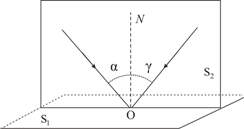
Definition 3Law of Light Reflection, is based on the fact that the incident and reflected rays, as well as the perpendicular to the interface between the two media, reconstructed at the point of incidence of the ray, are in the same plane (the plane of incidence). In this case, the angles of reflection and incidence, γ and α, respectively, are equal values.
Law of light refraction
Definition 4Law of light refraction, is based on the fact that the incident and refracted rays, as well as the perpendicular to the interface between two media, reconstructed at the point of incidence of the ray, lie in the same plane. The ratio of the sin angle of incidence α to the sin angle of refraction β is a value that is constant for the two given media:
sin α sin β = n .
The scientist W. Snell experimentally established the law of refraction in 1621.
Definition 5
Constant n – is the relative refractive index of the second medium relative to the first.
Definition 6
The refractive index of a medium relative to vacuum is called - absolute refractive index.
Definition 7
Relative refractive index of two media is the ratio of the absolute refractive indices of these media, i.e.:
The laws of refraction and reflection find their meaning in wave physics. Based on its definitions, refraction is the result of the transformation of the speed of wave propagation during the transition between two media.
Definition 8
Physical meaning of the refractive index is the ratio of the speed of wave propagation in the first medium υ 1 to the speed in the second υ 2:
Definition 9
The absolute refractive index is equivalent to the ratio of the speed of light in a vacuum c to the speed of light υ in the medium:
In Figure 3. 1. 1 illustrates the laws of reflection and refraction of light.
Figure 3. 1. 1. Laws of reflection υ refraction: γ = α; n 1 sin α = n 2 sin β.
Definition 10
A medium whose absolute refractive index is smaller is optically less dense.
Definition 11
Under conditions of light transition from one medium inferior in optical density to another (n 2< n 1) мы получаем возможность наблюдать явление исчезновения преломленного луча.
This phenomenon can be observed at angles of incidence that exceed a certain critical angle α p r. This angle is called the limiting angle of total internal reflection (see Fig. 3, 1, 2).
For the angle of incidence α = α p sin β = 1 ; value sin α p p = n 2 n 1< 1 .
Provided that the second medium is air (n 2 ≈ 1), then the equality can be rewritten as: sin α p p = 1 n, where n = n 1 > 1 is the absolute refractive index of the first medium.
Under the conditions of the glass-air interface, where n = 1.5, the critical angle is α p p = 42 °, while for the water-air interface n = 1. 33, and α p p = 48 , 7 ° .

Figure 3. 1. 2. Total internal reflection of light at the water-air interface; S – point light source.
The phenomenon of total internal reflection is widely used in many optical devices. One of such devices is a fiber light guide - thin, randomly curved threads made of optically transparent material, inside of which light entering the end can spread over enormous distances. This invention became possible only thanks to the correct application of the phenomenon of total internal reflection from lateral surfaces (Fig. 3. 1. 3).
Definition 12
Fiber optics is a scientific and technical direction based on the development and use of optical fibers.

Drawing 3 . 1 . 3 . Propagation of light in a fiber light guide. When the fiber is strongly bent, the law of total internal reflection is violated, and light partially exits the fiber through the side surface.

Drawing 3 . 1 . 4 . Model of reflection and refraction of light.
If you notice an error in the text, please highlight it and press Ctrl+Enter
OPTICAL PATH LENGTH is the product of the path length of a light beam and the refractive index of the medium (the path that light would travel during the same time, propagating in a vacuum).
Calculation of the interference pattern from two sources.
Calculation of the interference pattern from two coherent sources.
Let's consider two coherent light waves emanating from sources u (Fig. 1.11.).

The screen for observing the interference pattern (alternating light and dark stripes) will be placed parallel to both slits at the same distance. Let us denote x as the distance from the center of the interference pattern to the point P under study on the screen.
Let us denote the distance between the sources as d. The sources are located symmetrically relative to the center of the interference pattern. From the figure it is clear that

Hence
and the optical path difference is equal to
![]()
The path difference is several wavelengths and is always significantly smaller, so we can assume that Then the expression for the optical path difference will have the following form:
Since the distance from the sources to the screen is many times greater than the distance from the center of the interference pattern to the observation point, we can assume that. e.
Substituting value (1.95) into condition (1.92) and expressing x, we obtain that intensity maxima will be observed at values
![]() , (1.96)
, (1.96)
where is the wavelength in the medium, and m is the order of interference, and X max - coordinates of intensity maxima.
Substituting (1.95) into condition (1.93), we obtain the coordinates of the intensity minima
![]() , (1.97)
, (1.97)
An interference pattern will be visible on the screen, which looks like alternating light and dark stripes. The color of the light stripes is determined by the filter used in the installation.
The distance between adjacent minima (or maxima) is called the interference fringe width. From (1.96) and (1.97) it follows that these distances have the same value. To calculate the width of the interference fringe, you need to subtract the coordinate of the adjacent maximum from the coordinate value of one maximum
For these purposes, you can also use the coordinate values of any two adjacent minima.
Coordinates of intensity minima and maxima.
Optical length of ray paths. Conditions for obtaining interference maxima and minima.
In a vacuum, the speed of light is equal to , in a medium with a refractive index n the speed of light v becomes less and is determined by the relation (1.52)
The wavelength in vacuum, and in a medium, is n times less than in vacuum (1.54):
When moving from one medium to another, the frequency of light does not change, since secondary electromagnetic waves, emitted by charged particles in a medium, are the result of forced oscillations occurring at the frequency of the incident wave.
Let two point coherent light sources emit monochromatic light (Fig. 1.11). For them, the coherence conditions must be satisfied: To point P, the first ray travels in a medium with a refractive index - a path, the second ray passes in a medium with a refractive index - a path. The distances from the sources to the observed point are called the geometric lengths of the ray paths. The product of the refractive index of the medium and the geometric path length is called the optical path length L=ns. L 1 = and L 1 = are the optical lengths of the first and second paths, respectively.
Let u be the phase velocities of the waves.
The first ray will excite an oscillation at point P:
 , (1.87)
and the second ray is vibration
 , (1.88)
The phase difference between the oscillations excited by the rays at point P will be equal to:
 , (1.89)
The multiplier is equal to (- wavelength in vacuum), and the expression for the phase difference can be given the form
there is a quantity called the optical path difference. When calculating interference patterns, it is the optical difference in the path of the rays that should be taken into account, i.e., the refractive indices of the media in which the rays propagate.
From formula (1.90) it is clear that if the optical path difference is equal to an integer number of wavelengths in vacuum
then the phase difference and oscillations will occur with the same phase. Number m is called the order of interference. Consequently, condition (1.92) is the condition of the interference maximum.
If equal to half an integer number of wavelengths in vacuum,
![]() , (1.93)
, (1.93)
That ![]() , so that the oscillations at point P are in antiphase. Condition (1.93) is the condition of the interference minimum.
, so that the oscillations at point P are in antiphase. Condition (1.93) is the condition of the interference minimum.
So, if at a length equal to the optical path difference of the rays, an even number of half-wavelengths fits, then a maximum intensity is observed at a given point on the screen. If there is an odd number of half-wavelengths along the length of the optical ray path difference, then a minimum of illumination is observed at a given point on the screen.
Recall that if two ray paths are optically equivalent, they are called tautochronous. Optical systems - lenses, mirrors - satisfy the condition of tautochronism.
The basic laws of geometric optics have been known since ancient times. Thus, Plato (430 BC) established the law of rectilinear propagation of light. Euclid's treatises formulated the law of rectilinear propagation of light and the law of equality of angles of incidence and reflection. Aristotle and Ptolemy studied the refraction of light. But the exact wording of these laws of geometric optics Greek philosophers could not find it. Geometric optics is the limiting case of wave optics, when the wavelength of light tends to zero. The simplest optical phenomena, such as the appearance of shadows and the production of images in optical instruments, can be understood within the framework of geometric optics.
The formal construction of geometric optics is based on four laws established experimentally: · the law of rectilinear propagation of light; · the law of independence of light rays; · the law of reflection; · the law of refraction of light. To analyze these laws, H. Huygens proposed a simple and visual method, later called Huygens' principle .Each point to which light excitation reaches is ,in turn, center of secondary waves;the surface that envelops these secondary waves at a certain moment in time indicates the position of the front of the actually propagating wave at that moment.
Based on his method, Huygens explained straightness of light propagation and brought out laws of reflection And refraction .Law of rectilinear propagation of light :· light propagates rectilinearly in an optically homogeneous medium.Proof of this law is the presence of shadows with sharp boundaries from opaque objects when illuminated by small sources. Careful experiments have shown, however, that this law is violated if light passes through very small holes, and the deviation from straightness of propagation is greater, the smaller the holes .

The shadow cast by an object is determined by straightness of light rays in optically homogeneous media. Fig 7.1 Astronomical illustration rectilinear propagation of light and, in particular, the formation of umbra and penumbra can be caused by the shading of some planets by others, for example lunar eclipse , when the Moon falls into the Earth's shadow (Fig. 7.1). Due to the mutual movement of the Moon and the Earth, the shadow of the Earth moves across the surface of the Moon, and the lunar eclipse passes through several partial phases (Fig. 7.2).
Law of independence of light beams :· the effect produced by an individual beam does not depend on whether,whether other bundles act simultaneously or whether they are eliminated. By dividing the light flux into separate light beams (for example, using diaphragms), it can be shown that the action of the selected light beams is independent. Law of Reflection (Fig. 7.3): the reflected ray lies in the same plane as the incident ray and the perpendicular,drawn to the interface between two media at the point of impact;· angle of incidenceα equal to the angle of reflectionγ: α = γ
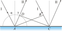
To derive the law of reflection Let's use Huygens' principle. Let us assume that a plane wave (wave front AB With, falls on the interface between two media (Fig. 7.4). When the wave front AB will reach the reflecting surface at the point A, this point will begin to radiate secondary wave .· For the wave to travel a distance Sun time required Δ t = B.C./ υ . During the same time, the front of the secondary wave will reach the points of the hemisphere, the radius AD which is equal to: υ Δ t= sun. The position of the reflected wave front at this moment in time, in accordance with Huygens’ principle, is given by the plane DC, and the direction of propagation of this wave is ray II. From the equality of triangles ABC And ADC flows out law of reflection: angle of incidenceα equal to the angle of reflection γ . Law of refraction (Snell's law) (Fig. 7.5): the incident ray, the refracted ray and the perpendicular drawn to the interface at the point of incidence lie in the same plane;· the ratio of the sine of the angle of incidence to the sine of the angle of refraction is a constant value for given media.


Derivation of the law of refraction. Let us assume that a plane wave (wave front AB), propagating in vacuum along direction I with speed With, falls on the interface with the medium in which the speed of its propagation is equal to u(Fig. 7.6). Let the time taken by the wave to travel the path Sun, equal to D t. Then BC = s D t. During the same time, the front of the wave excited by the point A in an environment with speed u, will reach points of the hemisphere whose radius AD = u D t. The position of the refracted wave front at this moment in time, in accordance with Huygens’ principle, is given by the plane DC, and the direction of its propagation - by ray III . From Fig. 7.6 it is clear that, i.e. .It follows from this Snell's law : A slightly different formulation of the law of propagation of light was given by the French mathematician and physicist P. Fermat.
Physical research relates mostly to optics, where he established in 1662 the basic principle of geometric optics (Fermat's principle). The analogy between Fermat's principle and the variational principles of mechanics played a significant role in the development of modern dynamics and the theory of optical instruments. According to Fermat's principle
, light propagates between two points along a path that requires least time.
Let us show the application of this principle to solving the same problem of light refraction. Ray from a light source S located in a vacuum goes to the point IN, located in some medium beyond the interface (Fig. 7.7). 
In every environment the shortest path will be straight S.A. And AB. Full stop A characterize by distance x from the perpendicular dropped from the source to the interface. Let's determine the time spent on traveling the path S.A.B.:![]() .To find the minimum, we find the first derivative of τ with respect to X and equate it to zero: , from here we come to the same expression that was obtained based on Huygens’ principle: Fermat’s principle has retained its significance to this day and served as the basis for the general formulation of the laws of mechanics (including the theory of relativity and quantum mechanics). From Fermat's principle has several consequences. Reversibility of light rays
: if you reverse the beam III (Fig. 7.7), causing it to fall onto the interface at an angleβ, then the refracted ray in the first medium will propagate at an angle α, i.e. it will go in the opposite direction along the beam I .
Another example is a mirage
, which is often observed by travelers on hot roads. They see an oasis ahead, but when they get there, there is sand all around. The essence is that in this case we see light passing over the sand. The air is very hot above the road itself, and in the upper layers it is colder. Hot air, expanding, becomes more rarefied and the speed of light in it is greater than in cold air. Therefore, light does not travel in a straight line, but along a trajectory with the shortest time, turning into warm layers of air. If light comes from high refractive index media
(optically more dense) into a medium with a lower refractive index
(optically less dense) ( > ) ,
for example, from glass into air, then, according to the law of refraction, the refracted ray moves away from the normal
and the angle of refraction β is greater than the angle of incidence α (Fig. 7.8 A).
.To find the minimum, we find the first derivative of τ with respect to X and equate it to zero: , from here we come to the same expression that was obtained based on Huygens’ principle: Fermat’s principle has retained its significance to this day and served as the basis for the general formulation of the laws of mechanics (including the theory of relativity and quantum mechanics). From Fermat's principle has several consequences. Reversibility of light rays
: if you reverse the beam III (Fig. 7.7), causing it to fall onto the interface at an angleβ, then the refracted ray in the first medium will propagate at an angle α, i.e. it will go in the opposite direction along the beam I .
Another example is a mirage
, which is often observed by travelers on hot roads. They see an oasis ahead, but when they get there, there is sand all around. The essence is that in this case we see light passing over the sand. The air is very hot above the road itself, and in the upper layers it is colder. Hot air, expanding, becomes more rarefied and the speed of light in it is greater than in cold air. Therefore, light does not travel in a straight line, but along a trajectory with the shortest time, turning into warm layers of air. If light comes from high refractive index media
(optically more dense) into a medium with a lower refractive index
(optically less dense) ( > ) ,
for example, from glass into air, then, according to the law of refraction, the refracted ray moves away from the normal
and the angle of refraction β is greater than the angle of incidence α (Fig. 7.8 A).

As the angle of incidence increases, the angle of refraction increases (Fig. 7.8 b, V), until at a certain angle of incidence () the angle of refraction is equal to π/2. The angle is called limit angle
. At angles of incidence α >
all incident light is completely reflected (Fig. 7.8 G).
· As the angle of incidence approaches the limiting one, the intensity of the refracted ray decreases, and the reflected ray increases. · If , then the intensity of the refracted ray becomes zero, and the intensity of the reflected ray is equal to the intensity of the incident one (Fig. 7.8 G).
· Thus,at angles of incidence ranging from to π/2,the beam is not refracted,and is fully reflected on the first Wednesday,Moreover, the intensities of the reflected and incident rays are the same. This phenomenon is called complete reflection.
The limit angle is determined from the formula: ![]() ;
;![]() .The phenomenon of total reflection is used in total reflection prisms
(Fig. 7.9).
.The phenomenon of total reflection is used in total reflection prisms
(Fig. 7.9). 
The refractive index of glass is n » 1.5, therefore the limiting angle for the glass-air interface = arcsin (1/1.5) = 42°. When light falls on the glass-air boundary at α > 42° there will always be total reflection. In Fig. Figure 7.9 shows total reflection prisms that allow: a) to rotate the beam by 90°; b) rotate the image; c) wrap the rays. Total reflection prisms are used in optical instruments (for example, in binoculars, periscopes), as well as in refractometers that make it possible to determine the refractive index of bodies (according to the law of refraction, by measuring , we determine the relative refractive index of two media, as well as the absolute refractive index of one of the media, if the refractive index of the second medium is known).

The phenomenon of total reflection is also used in light guides , which are thin, randomly curved threads (fibers) made of optically transparent material. Fig. 7.10 In fiber parts, glass fiber is used, the light-guiding core (core) of which is surrounded by glass - a shell made of another glass with a lower refractive index. Light incident on the end of the light guide at angles greater than the limit , undergoes at the core-shell interface total reflection and propagates only along the light guide core. Light guides are used to create high-capacity telegraph-telephone cables . The cable consists of hundreds and thousands of optical fibers as thin as human hair. Through such a cable, the thickness of an ordinary pencil, up to eighty thousand telephone conversations can be simultaneously transmitted. In addition, light guides are used in fiber-optic cathode ray tubes, in electronic counting machines, for encoding information, in medicine (for example, stomach diagnostics), for purposes of integrated optics.
Even before the nature of light was established, the following were known: laws of geometric optics(the question of the nature of light was not considered).
- 1. Law of independence of light rays: the effect produced by a single ray does not depend on whether other rays act simultaneously or are eliminated.
- 2. Law of rectilinear propagation of light: light propagates rectilinearly in a homogeneous transparent medium.
Rice. 21.1.
- 3. Law of light reflection: the reflected ray lies in the same plane with the incident ray and the perpendicular drawn to the interface between the two media at the point of incidence; the angle of reflection /|" is equal to the angle of incidence /, (Fig. 21.1): i[ = i x.
- 4. The law of light refraction (Snell’s law, 1621): incident ray, refracted ray and perpendicular
to the interface between two media, drawn at the point of incidence of the beam, lie in the same plane; when light is refracted at the interface between two isotropic media with refractive indices p x And n 2 condition is met
Total internal reflection- this is the reflection of a light beam from the interface between two transparent media in the case of its fall from an optically denser medium into an optically less dense medium at an angle /, > / pr, for which the equality holds
where "21 is the relative refractive index (case l, > n 2).
The smallest angle of incidence / at which all incident light is completely reflected into the medium / is called limit angle total reflection.
The phenomenon of total reflection is used in light guides and total reflection prisms (for example, in binoculars).
Optical path lengthL between points Lee W transparent medium is the distance over which light (optical radiation) would travel in a vacuum in the same time it takes to travel from A to IN in the environment. Since the speed of light in any medium is less than its speed in vacuum, then L always greater than the actual distance covered. In a heterogeneous environment
Where n- refractive index of the medium; ds- an infinitesimal element of the ray trajectory.
In a homogeneous medium, where the geometric path length of light is equal to s, the optical path length will be defined as

Rice. 21.2. Example of tautochronic light paths (SMNS" > SABS")
The last three laws of geometric optics can be obtained from Fermat's principle(c. 1660): In any medium, light travels along a path that requires the minimum amount of time to travel. In the case where this time is the same for all possible paths, all light paths between two points are called tautochronic(Fig. 21.2).
The tautochronism condition is satisfied, for example, by all paths of rays passing through the lens and producing an image S" light source S. Light travels along paths of unequal geometric length in the same time (Fig. 21.2). Exactly what is emitted from the point S rays simultaneously and after the shortest possible time are collected at a point S", allows you to obtain an image of the source S.
Optical systems is a set of optical parts (lenses, prisms, plane-parallel plates, mirrors, etc.) combined to obtain an optical image or to transform the light flux coming from a light source.
The following are distinguished: types of optical systems depending on the position of the object and its image: microscope (the object is located at a finite distance, the image is at infinity), telescope (both the object and its image are at infinity), lens (the object is located at infinity, and the image is at a finite distance) , projection system (the object and its image are located at a finite distance from the optical system). Optical systems are used in technological equipment for optical location, optical communications, etc.
Optical microscopes allow you to examine objects whose dimensions are smaller than the minimum eye resolution of 0.1 mm. The use of microscopes makes it possible to distinguish structures with a distance between elements of up to 0.2 microns. Depending on the tasks to be solved, microscopes can be educational, research, universal, etc. For example, as a rule, metallographic studies of metal samples begin using the method of light microscopy (Fig. 21.3). In the presented typical micrograph of the alloy (Fig. 21.3, A) it can be seen that the surface of aluminum-copper alloy foils is

Rice. 21.3.A- grain structure of the surface of the A1-0.5 at.% Cu alloy foil (Shepelevich et al., 1999); b- cross-section along the thickness of the foil of the Al-3.0 at.% Cu alloy (Shepelevich et al., 1999) (smooth side - the side of the foil in contact with the substrate during solidification) holds areas of smaller and larger grains (see subtopic 30.1 ). Analysis of the grain structure of the cross-section of the sample thickness shows that the microstructure of alloys of the aluminum - copper system varies along the thickness of the foils (Fig. 21.3, b).